The challenge: Testing business jet primary power distribution units.
customer requirements
The customer’s specification called for two floor-standing units to act as docking stations designed to accept left- and right-handed versions of trolley units carrying the distribution units. These trolleys allowed the distribution units to be easily hooked up outside the test system and then “parked” inside a garage-type construction. A self-test adapter was also required for identifying faults on the boards of the PXI chassis, and had to be constructed in such a way as to allow access for maintenance and repair purposes.
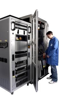
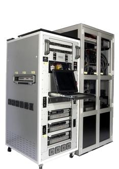
The heart of the test system is a National Instruments 19-inch rack-mounting PXI based computer equipped with dedicated I/O to control all sensors, actuators, switches and relays. An I/O multiplexer system is used to route various test points from the product under test to cards in the PXI chassis using serial communications, ARINC, RS232 and RS422 interfaces. The system also includes various power supplies for high- and low-current testing and interfaces using Virginia Panel Corporation Mass Interconnect solutions.
A key objective was to keep all instrumentation and rack-mount power supplies in a single mobile equipment rack beside the garage, and to separate the high-current switching and measurement devices inside the garage above and around the docking area. To permit easy connection a VPC G6 interface was used, allowing the signal wiring from the instrumentation and low-current power supplies to be disconnected from the garage. This concept is also useful for the self-test requirement as it allows the self-test adapter to be fitted to the VPC interface when the garage is disconnected.
To make the facility fail-safe, a fully functional emergency stop and interlock circuit has been created consisting of emergency “stop” buttons located at various points around the system along with door and panel interlock switches, temperature switches and smoke detectors. This protects the system in the event of the unit under test being manufactured incorrectly. “Watchdog” timers are also fitted to ensure that the system is shut down if the PXI chassis “crashes” and holds on to a load for longer than the prescribed time.
To provide suitable cooling of the equipment, a widened 19-inch rack is used to provide space for the high air-flow DC fans. These are strategically situated throughout the rack, with the high-current supplies (up to 1125 A at 28 V DC) being thermally separated using a thermal barrier foam.
Starting with electrical drawings and equipment lists, a 3D model of the equipment rack and garage was made using Solid Edge modelling software to ensure that all the required components fitted together correctly.
The structure of the equipment rack started with a 19-inch rack on wheels. To this rack was added shelving to hold the power supplies, PXI chassis and test equipment. In addition, custom-made panels and fascia plates were installed on the front and sides of the rack to hold various electrical components. Once the equipment was installed into the rack, the wiring of the 3-phase power distribution and safety circuits were completed and the custom cable assemblies from the instrumentation to the VPC interface added.
Owing to its size, the garage had to be designed and constructed using extruded aluminium sections. The frame was installed with thick fibreglass panels on the sides and an aluminium base and top to maintain stability. Large doors in the front and back and internal panels to fix electrical components were added. The unit was then completely hard-wired using wire gauges from 0.24 to 150 mm2.
Both trolleys were designed around each unit under test to allow precise alignment of the high-current connections to the distribution unit terminals. Storage for the signal harnesses and terminal tools was also provided inside the trolleys.